Alfa Laval Shutter Valve
Koltek valve is a manually or pneumatically operated valve, designed for use in the food, chemical, pharmaceutical and other industries where valves of sanitary design are needed.
Product Description
Working principle
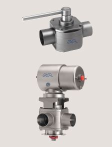
A PTFE shutter is operated by means of a handle or an actuator. A spring system presses the shutter against the inside cylindrical surface of the valve body thus ensuring complete tightness. The air actuated valve can be fitted with ThinkTop® or a laterally fitted indication unit for remote indication of the valve position. The manually operated valve can be fitted with laterally indication units (used for LKLA actuators). The actuator for the valve comes in two versions, single acting or double acting. The single acting actuator operates with one main piston whereas the double acting actuator operates with two main pistons.
Standard Design
The valve consist of a rigid body with an internal cylindrical bore and 2 or 3 ports for pipe connection. The two lids have guide rings or bearings for an internal shaft which supports and positions the shutter. The stainless steel handle or the actuator is fitted to turn the shaft. The actuator consists of a system of cylinders and one or two main pistons interconnected with a toothed bar which interacts with a gear wheel on the valve shaft. The system is insensitive to pressure shocks
in the valve.
Technical Data
Temperature
Max. temperature: . . . . . . . . . . . . . 110°C
Pressure
Max. pressure against shutter: . . . . . 300 kPa (3 bar)
Max. pressure behind shutter: . . . . . . 1000 kPa (10 bar
Air pressure for actuator: . . . . . . . . . Max. 800 kPa (8 bar)
Min. 500 kPa (5 bar)
Air Connections
Compressed air:
R 1/8″ (BSP), internal thread
Physical Data
Materials
Product wetted steel parts: . . . . . . . . 1.4404 (316L.)
Product wetted seals: . . . . . . . . . . . Shutter in PTFE
EPDM Actuator seals: . . . . . . . . . . . . . . . . NBR
Actuator functions
Actuator type 630:
– for 25 mm to 76.1 mm valves only
– two positions
– spring/air
– turning angle 1×90°
Actuator type 632:
– two positions
– air/air
– turning angle 1×180°

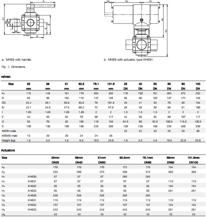
Dimensions (mm)
Caution, opening/closing time:
Opening/closing time will be affected by the following:
– The air supply (air pressure).
– The length and dimensions of the air hoses.
– Number of valves connected to the same air hose.
– Use of single solenoid valve for serial connected air actuator functions.
– Product pressure.
Pressure drop/capacity diagrams

Note!
For the diagram the following applies:
Medium: Water (20°C).
Measurement: In accordance with VDI 2173
Pressure drop can also be calculated in Anytime configurator.
Pressure drop can also be calculated with the following formula:
Q = Kv x √∆p
Where
Q = Flow in m3/h.
Kv = m3/h at a pressure drop of 1 bar (see table above).
∆ p = Pressure drop in bar over the valve.
How to calculate the pressure drop for an ISO 2.5″ shut-off valve if
the flow is 40 m3/h
2.5″ shut-off valve, where Kv = 111 (See table above).
Q = Kv x √∆p
40 = 111 x √∆p

Options
A. Male parts or clamp liners in accordance with required standard.
B. Control and Indication: IndiTop, ThinkTop or ThinkTop Basic.
C. Bottom lid for hot water or steam heating.
D. Bottom fitted indication unit.
E. Limit stop for MH 52/53.
F. Pilot valve, type L or T (for actuator type 633). Type L is used when two ThinkTop units are used.
G. Rebuilding to double acting value for high viscosity product or quick operation.
H. Product wetted seals of NBR or FPM..
Note! For further details, see also instruction IM 70735.
Bottom fitted indication units*
(together with bracket for indication unit)
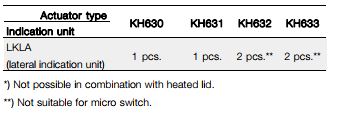
Note! For all manually operated valves: Use LKLA indication units