Alfa Laval Unique SSV Manually Operated/Manually Regulating
The Unique Single Seat valve meets the highest demands of your process in terms of hygiene and safety. It is built on a well-proven platform, from an installed base of more than one million valves.
Product Description
Working principle
The manual regulated Unique Single Seat Valve is a regulating valve used for manual control of pressure and flow. The valves permit gradual opening and the few and simple moving parts result in very reliable valves easy to dismantle. The plug can be fixed in the adjusted position with a lock screw. The valve is based on the modular platform of the Unique Single Seat Valve.
Standard Design
The manual operated valve can easily be converted to a pneumatic operated valve by replacing the crank mechanism with an actuator. The other parts are identical.
Technical Data
Temperature
Temperature range: . . . . . . . . . . . . . -10°C to +140°C (EPDM)
Pressure
Max product pressure: . . . . . . . . . . . 1000 kPa (10 bar)
Min. product pressure: . . . . . . . . . . Full vacuum
Valve Body Combinations

Physical Data
Materials
Product wetted steel parts: . . . . . . . 1.4404 (316L)
Other steel parts . . . . . . . . . . . . . . . 1.4301 (304)
External surface finish . . . . . . . . . . . Semi-bright (blasted)
Internal surface finish . . . . . . . . . . . . Bright (polished), Ra < 0.8 µm
Other product wetted seals . . . . . . . . EPDM
Options
A. Male parts or clamp liners in accordance with required standard.
B. Product wetted seals in HNBR or FPM.
C. Plug seal HNBR, FPM or TR2 plug (floating PTFE design – only for Manual Operated Valve).
D. External surface finish bright.
Note
For further details, see instruction ESE00307.
Other valves in the same basic design
The valve range includes several purpose built valves. Below listed are some of the valve models available, though please use the Alfa Laval computer aided selection tool (Anytime configurator) for full access to all models and options.
– Standard valve.
– Reverse acting valve.
– Aseptic valve.
– Long Stroke valve.
– Tank Outlet valve.
The actuator comes with a 5 years warranty
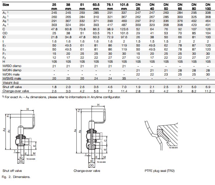
Dimensions (mm) – Unique Manually Operated Valves

Kv-Factors

* optional
Kv = m3/h at a pressure drop of 1 bar.
For other pressure drops than 1 bar the flow can be calculated with the following formula:
Q = Kv x √∆p
Where
Q = Flow in m3/h.
Kv = See above.
∆ p = Pressure drop in bar over the valve.
Example:
Plug Kv 75
Q to be calculated at ∆p = 2 bar:
Q = 75 x √2 = 106 m3/h
or at 50% stroke:
Q = 0.5 x 75 x √2 = 53 m3/h
Pressure drop/capacity diagram:
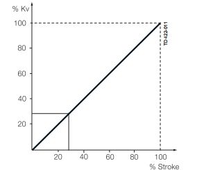
The plugs have linear characteristics. This means that a certain amount of throttling, by reducing the stroke, results in a proportional reduction of the flow if the pressure drop remains unchanged.

Fig. 3. The flow in % of the total flow at a pressure drop of 1 bar
Dimensions (mm) – Unique Manually Regulating Valve


