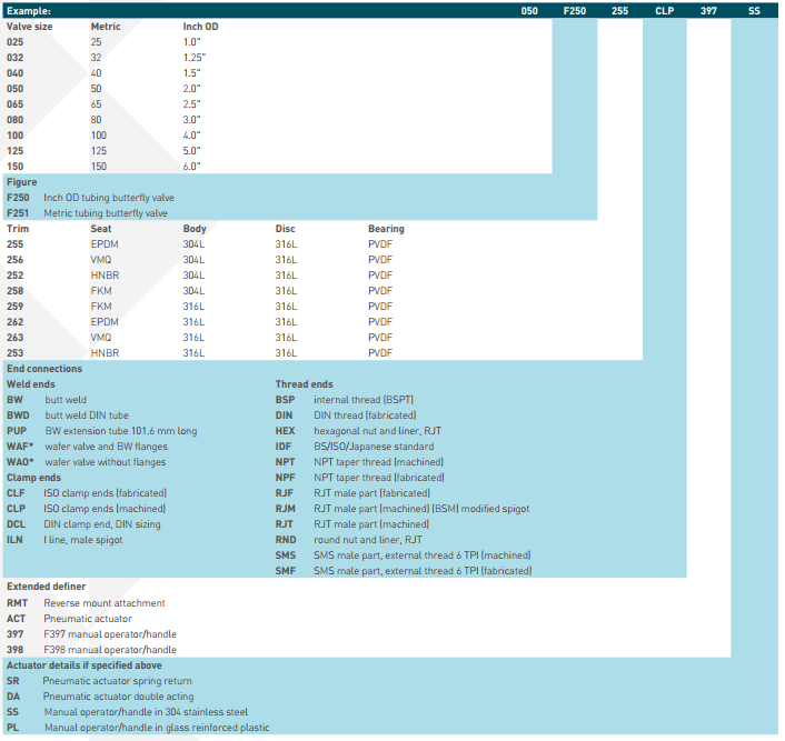
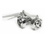
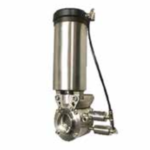
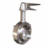
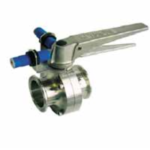
Pentair Hygienic Butterfly Valves F250/F251
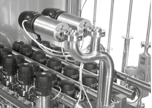
Pentair Hygienic Butterfly Valves F250/F251 are used in all segments of hygienic applications. Our comprehensive shut-off valve line features both manual and pneumatic drive options, including lockable handles and vertical actuators.
Product Description
General Application
A universal valve for isolation and control, in the food, dairy, brewing, pharmaceutical, beverage and chemical industries. The F250 and F251 are designed to be easily automated with any of PENTAIR’s actuators and controls.
From the F257 Vertical actuator and F783E Electronic control top, to the F79E/U or F79S Actuator.
Benefits
- Maintenance friendly.
- Site repairable.
- Quarter turn operation.
- Full range of optional accessories.
Features
- Quarter turn operation
- Isolation or regulation control
- Equal percentage characteristics
- Bi-directional capability
- Fully machined 316L stainless steel body
- Optional end connections
- One-piece disc and stem assembly
- High Cv slim profile disc
- Integral valve position indicator
- High grade seat material options
- Combination dual or multi position handle assembly
- High impact reinforced polymer handle with a stainless steel drive (full stainless steel option available)
- Integral padlocking as standard on manual valves
- Maintenance friendly
- Site repairable
- Full range of optional accessories
Functional description
Südmo Hygienic Butterfly Valves can be operated either by a manual handle or remotely controlled by an automated pneumatic actuator. The manual version comes standard with a dual/multiposition handle notch plate, which can be easily reconfigured to suit the specific installation by being positioned in any of the four operating quadrants, and also is supplied standard with a padlock facility.
The automated version valve can be supplied in three configurations, Spring to Close (STC), Spring to Open (STO) or Double acting (DA).
Technical data
Max. product pressure at 20°C: 10bar (1000kPa)
Min. product pressure at 20°C: Full vacuum
Recommended operating pressure at 20°C: 6bar (600kPa)
Recommended temperature range: -5°C to 95°C
Product Information
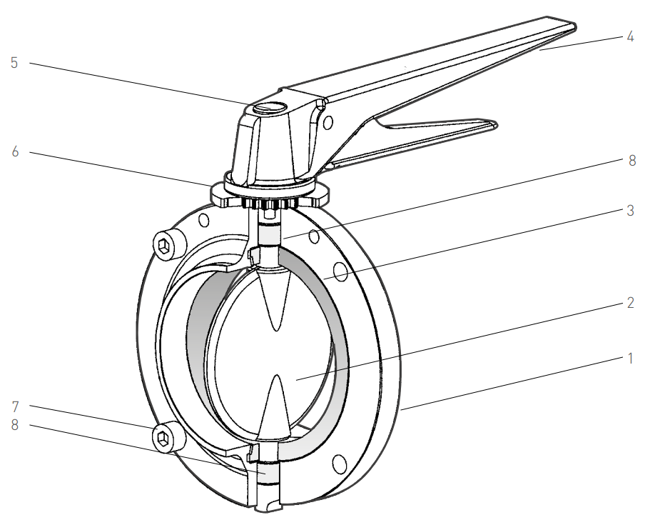
Parts List
| No. | Description | Material | Standard |
| 1 | Body | 316L (or 304L) stainless steel | ASTM A276 (or A182) |
| 2 | Disc stem | 316L stainless steel | ASTM A743 CF8M |
| 3 | Seat | VMQ (white) | FDA |
| EPDM (black) | FDA | ||
| NBR (black) | FDA | ||
| HNBR (black) | FDA | ||
| FKM (red) | FDA | ||
| 4 | Handle assembly | High impact glass reinforced polymer or 304 stainless steel | – |
| 5 | Handle plug/Screw | TPR / 304 stainless steel | Commercial |
| 6 | Notch plate | 304 stainless steel | ASTM A743 CF8 |
| 7 | Body fasteners | 304 stainless steel | ASTM A276 |
| 8 | Bearings | PVDF | Commercial |
Technical Data
| Max static temperature | |
| VMQ | 150°C |
| EPDM | 120°C |
| NBR | 100°C |
| HNBR | 150°C |
| FKM | 150°C |
NOTE: Although the various seat materials available can withstand temperatures above the max. recommended operating temperature for short periods of time, such as for sterilisation and certain applications, the servicability of these seats at elevated temperatures does vary depending on the media, pressure and other variables. Therefore, this is best determined from experience gained with the application concerned.
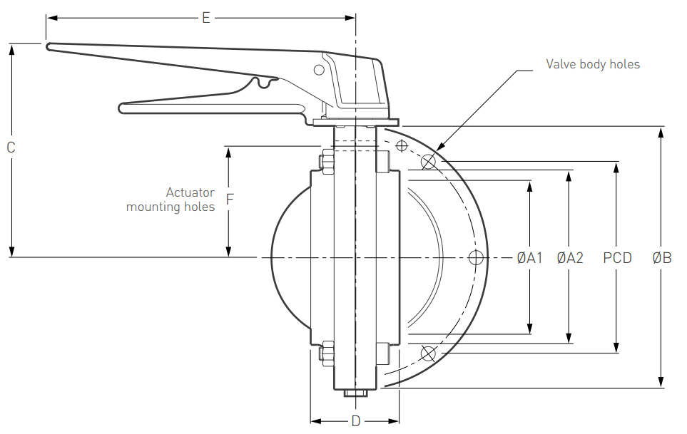
F250 Inch OD Valve Dimensions (mm)
| Valve size | ||||||||||||||
| DN | Inch OD | ØA1 | ØA2 | ØB | C | D | E | F | PCD | No. holes | Hole dia. | Stem conn. | Mass (kg) | Kv (Fully open) |
| 25 | 1.0” | 22.3 | 25.4 | 69 | 83.5 | 50 | 156 | 26.5 | 59 | 4 | 6 | 8 x 8 | 0.7 | 17 |
| 40 | 1.5” | 35.0 | 38.1 | 79 | 88.5 | 50 | 156 | 31.5 | 69 | 4 | 6 | 8 x 8 | 0.8 | 64 |
| 50 | 2.0” | 47.7 | 50.8 | 94 | 96.0 | 50 | 156 | 38.0 | 84 | 4 | 6 | 8 x 8 | 1.1 | 131 |
| 65 | 2.5” | 60.4 | 63.5 | 104 | 101 | 50 | 156 | 43.0 | 95 | 4 | 6 | 8 x 8 | 1.5 | 220 |
| 80 | 3.0” | 73.1 | 76.2 | 124 | 112.0 | 60 | 185 | 50.0 | 111 | 4 | 8 | 10 x 10 | 2.0 | 333 |
| 100 | 4.0” | 98.0 | 101.6 | 151 | 125.5 | 70 | 185 | 63.5 | 139 | 6 | 8 | 12 x 12 | 3.3 | 726 |
| 125 | 5.0” | 123.0 | 127.0 | 198 | 171.0 | 71 | 266 | 90.4 | 177 | 6 | 10 | 15 x 15 | 7.5 | 1370 |
| 150 | 6.0” | 148.4 | 152.4 | 223 | 183.5 | 80 | 266 | 98.5 | 207 | 6 | 10 | 15 x 15 | 8.2 | 2050 |
F251 Metric Valve Dimensions (mm)
| Valve size | ||||||||||||||
| DN | Metric | ØA1 | ØA2 | ØB | C | D | E | F | PCD | No. holes | Hole dia. | Stem conn. | Mass (kg) | Kv (Fully open) |
| 25 | 25 | 26 | 29 | 74 | 86.0 | 50 | 156 | 29.0 | 63 | 4 | 6 | 8 x 8 | 0.8 | 19 |
| 32 | 32 | 32 | 35 | 79 | 88.5 | 50 | 156 | 31.5 | 69 | 4 | 6 | 8 x 8 | 0.7 | 41 |
| 40 | 40 | 38 | 41 | 87 | 92.5 | 50 | 156 | 35.5 | 76 | 4 | 6 | 8 x 8 | 0.9 | 69 |
| 50 | 50 | 50 | 54 | 99 | 98.5 | 50 | 156 | 40.5 | 89 | 4 | 6 | 8 x 8 | 1.4 | 137 |
| 65 | 65 | 66 | 70 | 123 | 111.5 | 50 | 185 | 49.5 | 109 | 4 | 8 | 10 x 10 | 2.5 | 263 |
| 80 | 80 | 81 | 85 | 138 | 119.0 | 54 | 185 | 57.0 | 124 | 4 | 8 | 10 x 10 | 3.0 | 381 |
| 100 | 100 | 100 | 104 | 158 | 129.0 | 54 | 185 | 67.0 | 144 | 6 | 8 | 12 x 12 | 4.5 | 689 |
| 125 | 125 | 125 | 129 | 198 | 171.0 | 74 | 266 | 90.4 | 177 | 6 | 10 | 15 x 15 | 7.5 | 1370 |
| 150 | 150 | 150 | 154 | 223 | 183.5 | 80 | 266 | 99.5 | 203 | 6 | 10 | 15 x 15 | 8.2 | 2050 |
NOTE: Dimensions ‘D’ and ‘A2’ shown above, are for the butt weld configuration only. For other types of connections, refer to the following end connection data. Dimension ‘E’ is the maximum clearance length for either handle. Masses shown are for bare shafted butt weld valves only.
F250 Inch OD Valves – Available End Connections
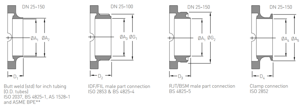
Dimensions (mm)
| D2 | D3 | D4 | |||||||||||||
| DN | Inch OD | ØA1 | ØA2 | ØA3 | ØA4 | ØA5 | ØG1 | ØG2 | D1M* | M* | F* | M* | F* | M* | F* |
| 25 | 1.0” | 22.3 | 25.4 | 23.0 | 23.0 | 50.5 | IDF 1” | RJT 1” | 25 | 40 | 46 | 40 | 50.5 | 40 | 37 |
| 40 | 1.5” | 35.0 | 38.1 | 35.6 | 35.6 | 50.5 | IDF 1 ½ ” | RJT 1 ½” | 25 | 40 | 46 | 40 | 50.5 | 40 | 37 |
| 50 | 2.0” | 47.7 | 50.8 | 47.7 | 47.7 | 64.0 | IDF 2” | RJT 2” | 25 | 40 | 46 | 40 | 50.5 | 40 | 37 |
| 65 | 2.5” | 60.4 | 63.5 | 59.4 | 60.4 | 77.5 | IDF 2 ½” | RJT 2 ½” | 25 | 50 | 46 | 50 | 50.5 | 40 | 37 |
| 80 | 3.0” | 73.1 | 76.2 | 72.2 | 73.1 | 91.0 | IDF 3” | RJT 3” | 30 | 50 | 51 | 46 | 55.5 | 40 | 42 |
| 100 | 4.0” | 98.5 | 101.6 | 98.5 | 98.0 | 119.0 | IDF 4” | RJT 4” | 35 | 52 | 64 | 52 | 60.5 | 46 | 50 |
| 125 | 5.0” | 123.0 | 127.0 | – | 123.0 | – | – | RJT 5” | 35 | – | – | – | 62.5 | – | 58 |
| 150 | 6.0” | 148.4 | 152.4 | – | 148.4 | 167.0 | – | RJT 6” | 40 | – | – | – | 65.5 | 55 | – |
NOTE: BSM modified version is available upon request, deduct 4.7 mm from dimension D3. *F Fabricated two piece body (Std.). *M Machined one piece body (on request). ** BPE is provided as Std. 1″ thru 4″ other sizes subject to enquiry.
Other Speciality Hygienic Butterfly Valve Options
- F250-1 Wafer Butterfly Valve.
For easy insertion and removal from inline service
- F250-1P Ski-Jump Powder Butterfly Valve.
For use with abrasive powder or granular products.
- F250T-1T Multi-Way Butterfly Valve
For divertion or convergence of fluids
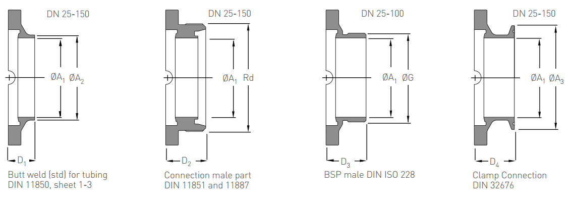
F251 Metric Valves – Available End Connections
Dimensions (mm)
| D1 | D2 | D3 | D4 | |||||||||
| DN | Metric | ØA1 | ØA2 | ØA3 | Rd | ØG | M* | F* | M* | F* | ||
| 25 | 25 | 26 | 29 | 50.5 | Rd 52 x ⅙” | G 1” | 25 | 37 | 53.5 | 34 | 34 | 46.0 |
| 32 | 32 | 32 | 35 | 50.5 | Rd 58 x ⅙” | G 1¼” | 25 | 37 | 56.5 | 34 | 34 | 46.0 |
| 40 | 40 | 38 | 41 | 50.5 | Rd 65 x ⅙” | G 1½” | 25 | 37 | 57.5 | 34 | 34 | 46.0 |
| 50 | 50 | 50 | 54 | 64.0 | Rd 78 x ⅙” | G 2” | 25 | 37 | 59.5 | 34 | 34 | 46.0 |
| 65 | 65 | 66 | 70 | 91.0 | Rd 95 x ⅙” | G 2½” | 25 | 41 | 64.5 | 37 | 37 | 52.5 |
| 80 | 80 | 81 | 85 | 106.0 | Rd 110 x ¼” | G 3” | 27 | 45 | 66.5 | 41 | 41 | 54.5 |
| 100 | 100 | 100 | 104 | 119.0 | Rd 130 x ¼” | G 4” | 27 | 45 | 80.5 | 41 | 41 | 54.5 |
| 125 | 125 | 125 | 129 | 155.0 | Rd 160 x ¼” | – | 37 | 58 | 82.5 | 50 | 50 | 64.5 |
| 150 | 150 | 150 | 154 | 183.0 | Rd 190 x ¼” | – | 40 | 66 | 89.5 | 55 | 55 | 64.5 |
NOTE: M* = Machined 1 piece body (Standard). F* = Fabricated 2 piece body (May apply for Imperalised DIN thread or other special cases)
Other Speciality Hygienic Butterfly Valve Options
- F250D-1D Double Block and Bleed Butterfly Valve
For safe separation of incompatible fluids.
- F250/1 Handle Extensions
For extension of valve stem, where extra handle clearance is needed for insulated pipes etc.
- F250/1 Proximity Kits
For feedback indication on manual valves.
F250 Pressure Drop / Flow Rates Graph
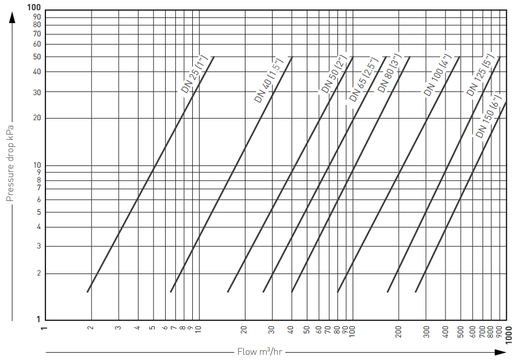
NOTE: This chart is based on a F250 valve fully open, using water at 20°C.
F251 Pressure Drop / Flow Rates Graph
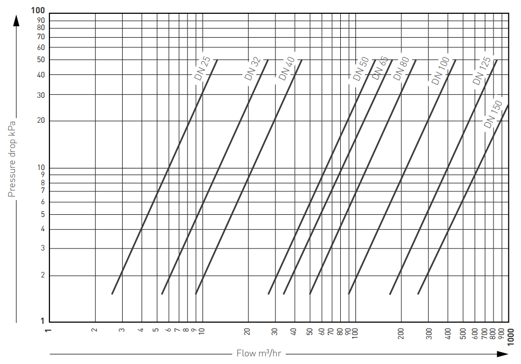
NOTE: This chart is based on a F251 valve fully open, using water at 20°C.
Selection Guide
